Recovery of Colour Information from B&W film telerecordings - James Insell 02/03/2007
1. Introduction
During the late 1960’s and early 1970’s, many B&W film telerecordings were constructed from PAL colour source material. Often these were filmed without the prior removal of the PAL chroma signal. A fine pattern of dots appears across areas of the resultant B&W film where objects portrayed had a coloured appearance originally.
In the past, ‘chroma dots’ have been regarded as a nuisance – since the observer sees a pattern of fine detail where no fine detail was originally present. The scanning and display of the films with the use of PAL equipment also gives rise to problems. A spurious chroma signal is regenerated and this can be misinterpreted by PAL equipment as a real chroma signal. Distracting flashing coloured patterns can result upon display. Telecine operators ensure that the chroma dots are filtered out when scanning this type of film recording.
It is the premise of this document that, rather than being regarded as a nuisance, the chroma dots embedded within this type of film recording could be usefully employed in the reconstruction of missing colour information. This information could be used to either directly recolour the B&W material, or to assist a separate process of colorisation.
2. An examination of source material
The below images show magnified sections taken from two different sources of the same individual frame of video material. Fig.2.1(a) shows a section taken from a VT copy of original video source. Fig. 2.1(b) shows a broadly similar section taken from a high-definition scan of a 16mm film recording negative.
|
|
|
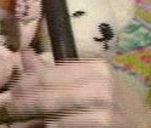
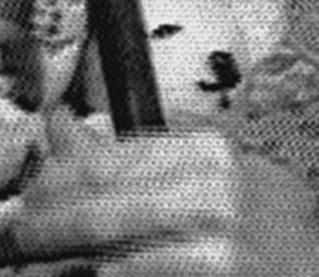
Fig. 2.1(a): Section from original video. Fig. 2.1(b): Section from film recording.
In fig. 2.1(a), there are contributions from around 100 lines of video. Half of the lines originate from the odd field and the other half originate from the even field. The lines from each field are interleaved in the image due to the effect of interlace. The ‘comb’ effect that can be seen along the top edge of the index finger portrayed in the image is due to the fact that the fields are separated in time by 1/50th second, and the object had a component of vertical motion.
In fig. 2.1(b), the same combing effect can be seen – showing that the film frame is also composed of contributions from two discrete fields. This also shows that the film recording system possessed a resolution sufficient for this level of detail to be captured.
Also in fig. 2.1(b), a pattern of finely spaced dots can be seen running horizontally along the length of the lines. These are seen due to the fact that the film has captured luminance + chroma and not just the luminance part of the PAL signal.
The chroma signal in PAL is a quadrature modulated signal derived from U and V (the colour difference signals). The sub-carrier used for colour modulation is a very precise 4.43361875MHz. Therefore, the horizontal spacing between dots represents exactly 2.2555 x 10⁻⁷ seconds (within an area of consistent hue).
The level of ‘presence’ of the dots is a measure of the saturation of the original colour. Broadly speaking, an area where no dots can be determined indicates an area where colour was weak or absent, and, an area where the presence of dots is very strong indicates an area of highly saturated colour.
Film recorders used a technique called ‘spot-wobble’ to obliterate the line-structure of the filmed monochrome CRT, but still retain vertical resolution. In effect, spot-wobble broadened the scanned path of the line on the CRT. Judging from fig. 2.1(b) and fig. 2.2, spot-wobble does not appear to have had much of a detrimental affect upon the presence of the chroma dots on film.[i]

Fig. 2.2: Distinctive chroma dot cross-hatching visible on areas corresponding with a saturated red colour.
3. Colour Information Recovery
There are a number of problems associated with obtaining usable colour information from the colour data which is embedded within certain film recordings. As described in the introduction, if PAL equipment is used for film scanning, a crude spurious PAL-like signal is reconstructed as a side-effect of the scanning process. When an attempt at decoding this is made by a PAL decoder within a PAL monitor various distracting and flashing spurious colours are produced.
When the film is scanned, the chroma is regenerated at approximately the correct frequency for PAL, but the geometrical distortion inherent in the film recording process scrambles, stretches and squeezes the signal. This, plus the absence of correctly timed colour bursts, means that the ‘chroma’ cannot be correctly demodulated using traditional PAL decoding techniques. These techniques generally rely on a stable relationship between the phase of the chroma signal and that of a local oscillator (which is a flywheel maintained by the frequency and phase of colour bursts). In addition, for correct decoding it would be necessary to know how the scanned lines are placed within the 8-field PAL colour sequence.
The geometrical distortion introduced during the film recording process means that the original television scan lines do not align correctly with those constructed during scanning. Any component of tilt to the scanned lines with-respect-to the original film recorder CRT lines would mean that the original lines are not tracked correctly by the telecine scan lines. The resultant ‘line’ would be made of contributions from a number of ‘original lines’ – and even from lines of the alternate original field. In addition, the lines laid out on the film are unlikely to be perfectly straight, and this provides another obstacle for correct tracking.
If it were possible to obtain satisfactory chroma/luma separation, and decode stable U and V values from the embedded chroma dots, then these could be used in conjunction with Y values derived from the film to create a full colour version of material.
3.1 Reversal of geometrical distortion
It appears that if it were possible to exactly track the original TV scan lines with those created at the time of telecine scanning then it may be possible to reconstruct a viable PAL signal. One would also need to compensate for the stretching/squeezing of the signal introduced by the horizontal element of geometric distortion, and introduce new colour bursts at the appropriate positions within the reconstructed signal.
Scanning the film in high-definition would be necessary in order to capture the required chroma data.
One idea muted for this type of signal reconstruction would be to employ block matching or phase correlation techniques on an HD scanned film recording in conjunction with a poor quality video copy of the same material.[ii] If the HD scan of the film was synchronised with the poor quality video then specially written software could be used to analyse each frame of material and create a spatial mapping between positions of objects on the film with those of the poor quality video. The spatial mapping between the two sources would make it possible to ‘DVE’ each area of a film recording frame back to the correct positions. An exact match would be required in order for satisfactory PAL decoding.
Hover your mouse over the images for a rough demonstration of how a film frame can be spatially undistorted to match an original VT source.
A new spatial mapping for each frame would probably need to be created – as opposed to one ‘generic mapping’ for use throughout the programme. This would be necessary in order to counter the effects of film hop and weave, and the ‘EHT breathing’ of the CRT in the original film-telerecorder.
A side-effect of this process would also be the recovery of temporal information. The two video fields (which are ‘locked together’ in the film frame) could be separated and the ‘video-look’ restored to the picture.
3.2 Advanced PAL decoding techniques
Whilst traditional PAL decoding techniques rely on chroma demodulation through the maintenance of a local colour subcarrier reference – crystal locked in both frequency and phase with that used at the time of modulation – it may be possible to explore new ideas for PAL decoding which do not rely upon the precise relationship between local-subcarrier and chroma phase.
One possibility is to put the complex problem of PAL signal recreation (3.1) to one side and look at other means that could be used for ‘localised decoding’ of the chroma dot pattern. These ideas could draw on the fact that two ‘line-locked’ fields are present on the film and each has been subject to exactly the same geometrical distortion as the other. Knowledge of the assembly of a PAL signal may lead to development of a decoding technique based on the chroma phase relationships between adjacent lines within the film frame. If an assumption was made that two adjacent lines shared the same hue then the chroma phase relationship between them could be used to derive the value of that hue. (It would also be necessary to determine nature of the lines used for localised decoding – such as field order - but this information could be obtained through trial and error, based on line spacings and placement within the film frame).
Similarly, it may be possible to achieve luma/chroma separation with this approach – possibly with a form of comb filter.
4. Helper information for Colourisation techniques
Full, and automated, decoding of the embedded chroma dots may be a tall order. Even if the problem proved tractable, the results may end up being quite noisy. However, it may still be possible to derive useful information about colour from the B&W film recordings. This could be used to assist a separate process of colourisation.
Colourisation relies on defining the colour of objects that appear numerous times within the duration of a programme. Where programme material is purely black and white, the colourist relies on building up a palette of object colours from collections of colour photographs and other reference material. Educated guesses are made for some objects.
4.1 Reconstruction of Colour Saturation values
A reasonably straightforward way to assist colorisation of the B&W telerecording would be to extract values for colour saturation. This could be achieved through means of a sub-carrier notch filter. The level of filtered ‘chroma’ (co-sited with luminance) would be directly proportional to the saturation of the original colour at this spatial position. In an HSV colour space, the recolourist would then only be required to set the hue of objects within the frame.
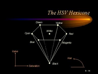
Fig. 4.1: The Hue-Saturation-Value colourspace.
4.2 Production of a colour palette
If a colourist were having difficulty in determining the colour of certain objects from available reference material, it may be possible to analyse chroma dot patterns in isolation through a semi-automated colour determining process.
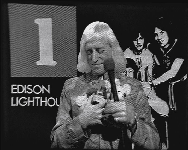
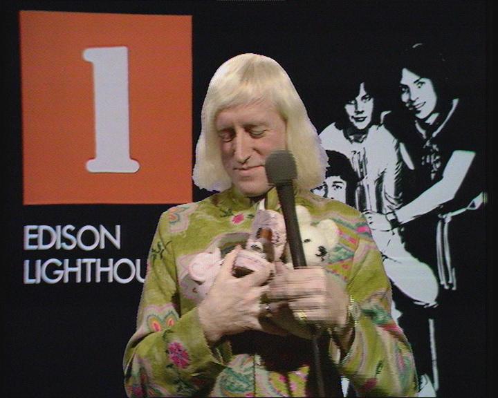
Even the semi-spurious colours created through use of PAL equipment for scanning and display can be used to assist colourisation. Fig. 4.2 shows a single frame captured from such a process. From this it can reasonably safely be determined that the drummer was wearing a red shirt and that the saxophone player in the middle was wearing a salmon colour shirt.
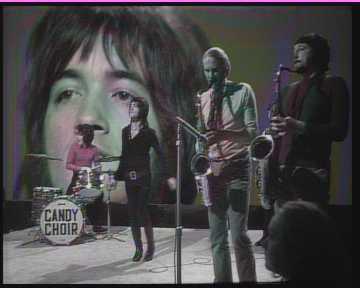
Fig. 4.2: Image captured from the output of a PAL decoder being fed by a standard-definition scan of a candidate film recording.
Other analysis techniques could be used, such as reduced forms of those described in section 3, or possibly even pattern recognition. Table 4.3 shows a selection of colours with corresponding patterns taken from a contrived chroma dot frame of colour bars.[iii] The patterns change according to the PAL eight-field sequence. Perhaps analysis over a number of frames would be required.
|
White |
|
|
Yellow |
|
|
Cyan |
|
|
Green |
|
|
Magenta |
|
|
Red |
|
|
Blue |
|
|
Black |
|


Table 4.3: Chroma dot patterns for a selection of colour co-ordinates.
4.3 Geometric ‘undistortion’ as an aid to reapplication of colour from a poor quality colour source
The traditional approach to reapplication of colour to B&W film-recordings from poor quality colour sources has involved a stage of spatial alignment between the film-recording and a colour off-air domestic recording. Due to the complex nature of the geometric distortion inherent in the film-recording, it has been necessary to use a video effects box (e.g. Charisma) to apply differing amounts of ‘warping’ to the various areas of the picture.[iv] This is a time-consuming process and relies on the care of a skilled operator to achieve a reasonable match. Even then, the alignment is not perfect and can wander from frame-to-frame, shot-to-shot, or over the course of the programme.
If the alignment technique described in 3.1 was developed, but shown not to give the exacting alignment required for the purposes of PAL signal recreation, then it may still be good enough to be used as a replacement for the ‘Charisma stage’ of in the recolourising of B&W film recordings.
Ideally an HD scan of the film would be used as a source, but the technique may still show promise when used in conjunction with an SD scan.
5. Research Proposal
It has already been established through study of a sample of the candidate film recordings that they can contain useful colour information (as can be seen from fig. 4.2). It has also been established through development of experimental software that the process of ‘undistortion’ described in 3.1 and 4.3 has potential.
A step-by-step approach to future research is proposed.
i). A sample of a candidate film recording frame will be taken and manually aligned with a new destination video image structure.
ii). Trial attempts will then be made at chroma/luma separation and PAL decoding using existing and newly devised experimental techniques. The outcome from this will demonstrate the practicality of PAL signal reconstruction (3.1) and inform choice of chroma separation and decoding technique. The decoded image will also give a level of confidence as to the quality of colour produced and the noise contained. The work may also lead to a successful direct decoding technique emerging (– as surmised in 3.2). It may also lead to a method and software for semi-automated colour palette creation (4.2), or filters that can be used to extract colour saturation information (4.1).
ii). The experimental software used to show the potential of advanced alignment techniques will be further refined. The existing, block matching, approach will be extended to exclude low-confidence matches from the input to a spatial map. A higher-quality ‘warping’ algorithm will be incorporated to replace the existing crude block-based ‘undistorer’.
The quality of the results achieved could promote the replacement of the ‘block-matching’ technique with more robust matching technique such as phase-correlation.
The work may result in the ability to directly retrieve a colour signal from the embedded chroma dots (3.1). If, ultimately, direct colour decoding proves unsuccessful then the technique will still have use in re-application of colour from poor quality sources (4.3).